pfSense® High Availability
In this configuration we will have 4 network interfaces. SYNC, dedicated to state and configurations synchronization. WAN for external connections. MGMT, dedicated to pfSense® management. DMZ, for internal servers.
I omit LAN interface because for this porpuse is not necessary, some tests will make from a management pc, on MGMT network.
Ip Address and diagram
First of all it’s necessary to make plan of work.
1- ip address assignments
2- network diagram (logical and fisical)
3- servers naming
Note
All public IP addresses are taken from IP reserved by IETF (TEST-NET-3) documentation and examples.
WAN Addressing
The WAN network is assigned by your ISP, tipically is a `/29` network.
For HA systems it’s necessary to have 3 ip address, one for each interface and one for virtual interface called CARP.
To connect each nodes to te internet it needed a Gateway and a pair of DNS server, for this lab use a Google DNS: 8.8.8.8 and 8.8.4.4.
IP Address |
Interface |
Node |
|---|---|---|
|
CARP |
Shared on all Nodes |
|
WAN |
Primary Node |
|
WAN |
Secondary Node |
MGMT Addressing
The MGMT network is private and protected network used only for network mangement.
Best practice is to choose, a non-canonical ip address like 192.168.0.0/24 to avoid future overlaps.
IP Address |
Interface |
Node |
|---|---|---|
|
CARP |
Shared on all Nodes |
|
MGMT |
Primary Node |
|
MGMT |
Secondary Node |
DMZ Addressing
The DMZ network is tipically a public network asigned by your ISP, in this example we will use
a private network with NAT.
Best practice is to choose, a non-canonical ip address like 192.168.0.0/24 to avoid future overlaps.
IP Address |
Interface |
Node |
|---|---|---|
|
CARP |
Shared on all Nodes |
|
DMZ |
Primary Node |
|
DMZ |
Secondary Node |
SYNC Addreessing
The SYNC network is a private and protected subnet, only pfSense® nodes need comunicate with this interfaces, and not need CARP virtual ip.
IP Address |
Interface |
Node |
|---|---|---|
|
SYNC |
Primary Node |
|
SYNC |
Secondary Node |
Network diagram
The network diagram show how pfSense® and network switchs are plugged.
This diagram is valid for both fisical and virtual devices.
For complete High Availability system, the network must also be totally redundant, in this example only the ISP router is not redundant.
whether you use switchs for each subnet, or vlans the logical connection diagram remains the same.
In this documents i provide two diagram; logical and fisical.
Attention
This documents not provide how configure switchs for VLANs or STP.
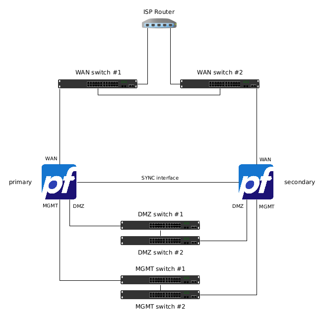
HA Fisical Diagram
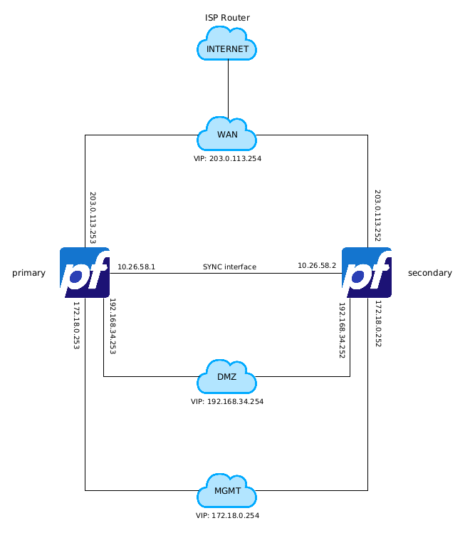
HA Logical Diagram
Cluster Configuration Basics
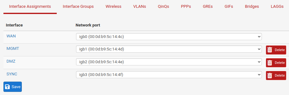
Install the OS and assign the interface at the same order on both nodes, like this, it is suggested to set the ip addresses in static mode.
Warning
If the interface are not aligned, configurations synchronization and other task will not work properly. Every interface additionally configuration must be replicated on all nodes.
Best practice is to assign interface and ip address from console for WAN and LAN as explain below and change LAN name in MGMT from web GUI.
Set correct DHCP pool, only on Primary node.
  1FreeBSD/amd64 (pfSense.home.arpa) (ttyu0)
  2
  3pfSense - Netgate Device ID: 98f0e53206c36b104aff
  4
  5*** Welcome to pfSense 2.6.0-RELEASE (amd64) on pfSense ***
  6
  7 WAN (wan)       -> igb0       ->
  8 LAN (lan)       -> igb1       -> v4: 192.168.1.1/24
  9
 10 0) Logout (SSH only)                  9) pfTop
 11 1) Assign Interfaces                 10) Filter Logs
 12 2) Set interface(s) IP address       11) Restart webConfigurator
 13 3) Reset webConfigurator password    12) PHP shell + pfSense tools
 14 4) Reset to factory defaults         13) Update from console
 15 5) Reboot system                     14) Enable Secure Shell (sshd)
 16 6) Halt system                       15) Restore recent configuration
 17 7) Ping host                         16) Restart PHP-FPM
 18 8) Shell
 19
 20Enter an option: 2
 21
 22Available interfaces:
 23
 241 - WAN (igb0 - dhcp, dhcp6)
 252 - LAN (igb1 - static)
 26
 27Enter the number of the interface you wish to configure: 1
 28
 29Configure IPv4 address WAN interface via DHCP? (y/n) n
 30
 31Enter the new WAN IPv4 address.  Press <ENTER> for none:
 32> 203.0.113.253
 33
 34Subnet masks are entered as bit counts (as in CIDR notation) in pfSense.
 35e.g. 255.255.255.0 = 24
 36     255.255.0.0   = 16
 37     255.0.0.0     = 8
 38
 39Enter the new WAN IPv4 subnet bit count (1 to 32):
 40> 29
 41
 42For a WAN, enter the new WAN IPv4 upstream gateway address.
 43For a LAN, press <ENTER> for none:
 44> 203.0.113.249
 45
 46Configure IPv6 address WAN interface via DHCP6? (y/n) n
 47
 48Enter the new WAN IPv6 address.  Press <ENTER> for none:
 49>
 50Disabling IPv4 DHCPD...
 51Disabling IPv6 DHCPD...
 52
 53Do you want to revert to HTTP as the webConfigurator protocol? (y/n) n
 54
 55Please wait while the changes are saved to WAN...
 56 Reloading filter...
 57 Reloading routing configuration...
 58 DHCPD...
 59
 60The IPv4 WAN address has been set to 203.0.113.253/29
 61
 62Press <ENTER> to continue.
 63pfSense - Netgate Device ID: 98f0e53206c36b104aff
 64
 65*** Welcome to pfSense 2.6.0-RELEASE (amd64) on pfSense ***
 66
 67 WAN (wan)       -> igb0       -> v4: 203.0.113.253/29
 68 LAN (lan)       -> igb1       -> v4: 192.168.1.1/24
 69
 70 0) Logout (SSH only)                  9) pfTop
 71 1) Assign Interfaces                 10) Filter Logs
 72 2) Set interface(s) IP address       11) Restart webConfigurator
 73 3) Reset webConfigurator password    12) PHP shell + pfSense tools
 74 4) Reset to factory defaults         13) Update from console
 75 5) Reboot system                     14) Enable Secure Shell (sshd)
 76 6) Halt system                       15) Restore recent configuration
 77 7) Ping host                         16) Restart PHP-FPM
 78 8) Shell
 79
 80Enter an option: 2
 81
 82Available interfaces:
 83
 841 - WAN (igb0 - static)
 852 - LAN (igb1 - static)
 86
 87Enter the number of the interface you wish to configure: 2
 88
 89Enter the new LAN IPv4 address.  Press <ENTER> for none:
 90> 172.18.0.253
 91
 92Subnet masks are entered as bit counts (as in CIDR notation) in pfSense.
 93e.g. 255.255.255.0 = 24
 94     255.255.0.0   = 16
 95     255.0.0.0     = 8
 96
 97Enter the new LAN IPv4 subnet bit count (1 to 32):
 98> 24
 99
100For a WAN, enter the new LAN IPv4 upstream gateway address.
101For a LAN, press <ENTER> for none:
102>
103
104Enter the new LAN IPv6 address.  Press <ENTER> for none:
105>
106
107Do you want to enable the DHCP server on LAN? (y/n) y
108Enter the start address of the IPv4 client address range: 172.18.0.10
109Enter the end address of the IPv4 client address range: 172.18.0.20
110Disabling IPv6 DHCPD...
111
112Do you want to revert to HTTP as the webConfigurator protocol? (y/n) n
113
114Please wait while the changes are saved to LAN...
115 Reloading filter...
116 Reloading routing configuration...
117 DHCPD...
118
119The IPv4 LAN address has been set to 172.18.0.253/24
120You can now access the webConfigurator by opening the following URL in your web browser:
121                https://172.18.0.253/
122
123Press <ENTER> to continue.
124pfSense - Netgate Device ID: 98f0e53206c36b104aff
125
126*** Welcome to pfSense 2.6.0-RELEASE (amd64) on pfSense ***
127
128 WAN (wan)       -> igb0       -> v4: 203.0.113.253/29
129 LAN (lan)       -> igb1       -> v4: 172.18.0.253/24
130
131 0) Logout (SSH only)                  9) pfTop
132 1) Assign Interfaces                 10) Filter Logs
133 2) Set interface(s) IP address       11) Restart webConfigurator
134 3) Reset webConfigurator password    12) PHP shell + pfSense tools
135 4) Reset to factory defaults         13) Update from console
136 5) Reboot system                     14) Enable Secure Shell (sshd)
137 6) Halt system                       15) Restore recent configuration
138 7) Ping host                         16) Restart PHP-FPM
139 8) Shell
140
141Enter an option:
  1FreeBSD/amd64 (pfSense.home.arpa) (ttyu0)
  2
  3pfSense - Netgate Device ID: 72278514ec4359e94ac9
  4
  5*** Welcome to pfSense 2.6.0-RELEASE (amd64) on pfSense ***
  6
  7 WAN (wan)       -> igb0       ->
  8 LAN (lan)       -> igb1       -> v4: 192.168.1.1/24
  9
 10 0) Logout (SSH only)                  9) pfTop
 11 1) Assign Interfaces                 10) Filter Logs
 12 2) Set interface(s) IP address       11) Restart webConfigurator
 13 3) Reset webConfigurator password    12) PHP shell + pfSense tools
 14 4) Reset to factory defaults         13) Update from console
 15 5) Reboot system                     14) Enable Secure Shell (sshd)
 16 6) Halt system                       15) Restore recent configuration
 17 7) Ping host                         16) Restart PHP-FPM
 18 8) Shell
 19
 20Enter an option: 2
 21
 22Available interfaces:
 23
 241 - WAN (igb0 - dhcp, dhcp6)
 252 - LAN (igb1 - static)
 26
 27Enter the number of the interface you wish to configure: 1
 28
 29Configure IPv4 address WAN interface via DHCP? (y/n) n
 30
 31Enter the new WAN IPv4 address.  Press <ENTER> for none:
 32> 203.0.113.252
 33
 34Subnet masks are entered as bit counts (as in CIDR notation) in pfSense.
 35e.g. 255.255.255.0 = 24
 36     255.255.0.0   = 16
 37     255.0.0.0     = 8
 38
 39Enter the new WAN IPv4 subnet bit count (1 to 32):
 40> 29
 41
 42For a WAN, enter the new WAN IPv4 upstream gateway address.
 43For a LAN, press <ENTER> for none:
 44> 203.0.113.249
 45
 46Configure IPv6 address WAN interface via DHCP6? (y/n) n
 47
 48Enter the new WAN IPv6 address.  Press <ENTER> for none:
 49>
 50Disabling IPv4 DHCPD...
 51Disabling IPv6 DHCPD...
 52
 53Do you want to revert to HTTP as the webConfigurator protocol? (y/n) n
 54
 55Please wait while the changes are saved to WAN...
 56 Reloading filter...
 57 Reloading routing configuration...
 58 DHCPD...
 59
 60The IPv4 WAN address has been set to 203.0.113.252/29
 61
 62Press <ENTER> to continue.
 63pfSense - Netgate Device ID: 72278514ec4359e94ac9
 64
 65*** Welcome to pfSense 2.6.0-RELEASE (amd64) on pfSense ***
 66
 67 WAN (wan)       -> igb0       -> v4: 203.0.113.252/29
 68 LAN (lan)       -> igb1       -> v4: 192.168.1.1/24
 69
 70 0) Logout (SSH only)                  9) pfTop
 71 1) Assign Interfaces                 10) Filter Logs
 72 2) Set interface(s) IP address       11) Restart webConfigurator
 73 3) Reset webConfigurator password    12) PHP shell + pfSense tools
 74 4) Reset to factory defaults         13) Update from console
 75 5) Reboot system                     14) Enable Secure Shell (sshd)
 76 6) Halt system                       15) Restore recent configuration
 77 7) Ping host                         16) Restart PHP-FPM
 78 8) Shell
 79
 80Enter an option: 2
 81
 82Available interfaces:
 83
 841 - WAN (igb0 - static)
 852 - LAN (igb1 - static)
 86
 87Enter the number of the interface you wish to configure: 2
 88
 89Enter the new LAN IPv4 address.  Press <ENTER> for none:
 90> 172.18.0.252
 91
 92Subnet masks are entered as bit counts (as in CIDR notation) in pfSense.
 93e.g. 255.255.255.0 = 24
 94     255.255.0.0   = 16
 95     255.0.0.0     = 8
 96
 97Enter the new LAN IPv4 subnet bit count (1 to 32):
 98> 24
 99
100For a WAN, enter the new LAN IPv4 upstream gateway address.
101For a LAN, press <ENTER> for none:
102>
103
104Enter the new LAN IPv6 address.  Press <ENTER> for none:
105>
106
107Do you want to enable the DHCP server on LAN? (y/n) n
108Disabling IPv4 DHCPD...
109Disabling IPv6 DHCPD...
110
111Do you want to revert to HTTP as the webConfigurator protocol? (y/n) n
112
113Please wait while the changes are saved to LAN...
114 Reloading filter...
115 Reloading routing configuration...
116 DHCPD...
117
118The IPv4 LAN address has been set to 172.18.0.252/24
119You can now access the webConfigurator by opening the following URL in your web browser:
120                https://172.18.0.252/
121
122Press <ENTER> to continue.
123pfSense - Netgate Device ID: 72278514ec4359e94ac9
124
125*** Welcome to pfSense 2.6.0-RELEASE (amd64) on pfSense ***
126
127 WAN (wan)       -> igb0       -> v4: 203.0.113.252/29
128 LAN (lan)       -> igb1       -> v4: 172.18.0.252/24
129
130 0) Logout (SSH only)                  9) pfTop
131 1) Assign Interfaces                 10) Filter Logs
132 2) Set interface(s) IP address       11) Restart webConfigurator
133 3) Reset webConfigurator password    12) PHP shell + pfSense tools
134 4) Reset to factory defaults         13) Update from console
135 5) Reboot system                     14) Enable Secure Shell (sshd)
136 6) Halt system                       15) Restore recent configuration
137 7) Ping host                         16) Restart PHP-FPM
138 8) Shell
139
140Enter an option:
Interface on Primary Node
Connect a management pc on LAN network and set it’s network interface in DHCP mode, access to pfSense® from browser at this URL; https://172.18.0.253. When running wizard set admin password, hostname, domain and DNS, leave all as default for WAN interface, and change the LAN name to MGMT, leave the rest at default. Now set other interface from web GUI and assign the chosen ip address. The final result must be as below.
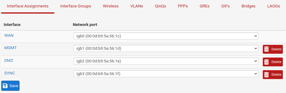
Primary Node Interfaces
SYNC Setup on Primary Node
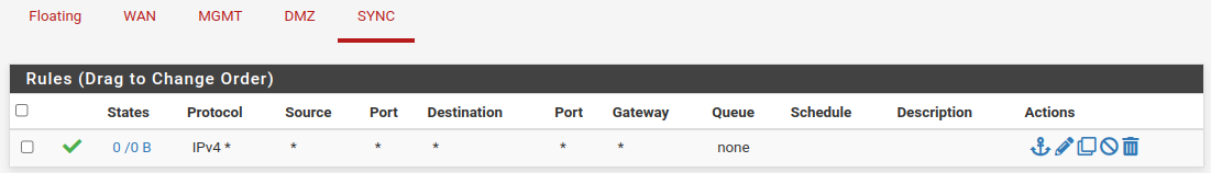
Firts step for activate Sync Setup is make a firewall rule on SYNC interface for communications between nodes.
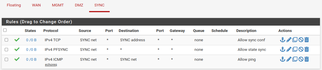
SYNC Rules on Primary
Now create a user syncUSER with “System - HA node sync” privilege and keep in mind the password.
Navigate to System → User Manager → Users.
Click
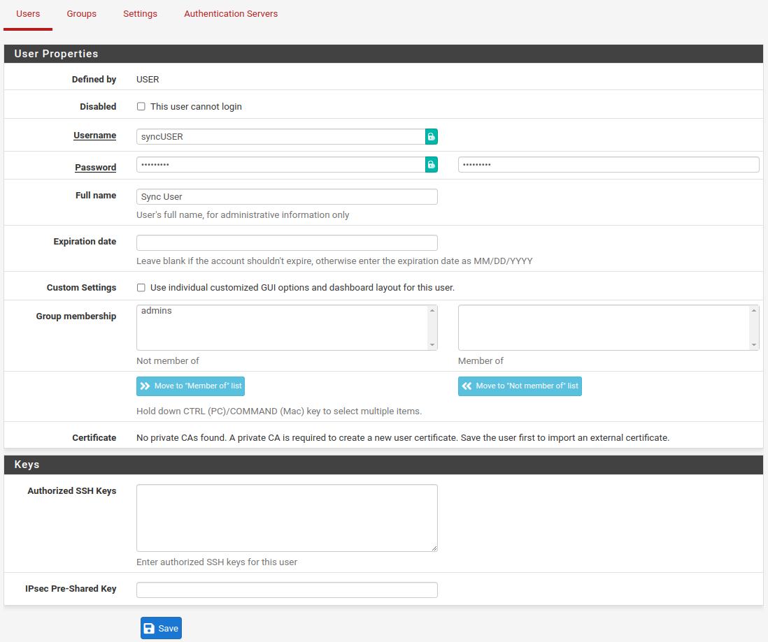
Sync User Creation [part 1]
Click
Now edit user syncUSER by click on  and add Effective Privileges to “System - HA node sync”.
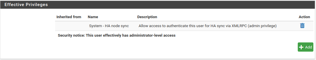
Sync User Creation [part 2]
Interface on Secondary Node
Connect a management pc on LAN network and set it’s network interface in DHCP mode, access to pfSense® from browser at this URL; https://172.18.0.252.
When running wizard set admin password and leave all as default for WAN interface, and change the LAN name to MGMT, leave the rest at default.
Now set other interface from web GUI and assign the chosen ip address.
The final result must be as below.
Secondary Node Interfaces
SYNC Setup on Secondary Node
Firts step for activate Sync Setup is make a firewall rule on SYNC interface for communications between nodes.
Set rule as premit any any, this rule will overwritten after configuration synchronization.
SYNC Rules on Secondary
Now create a user with “System - HA node sync” privilege identically at user created on Primary node, including the password.
State Synchronization Settings (pfsync) on Primary Node
For synchronization process to use pfsync, an utility that perform states synchronizations between pfSense®.
Navigate to System → High Avail. Sync.
- Synchronize States:
checked
- Synchronize Interface:
SYNC
- Sinchronize Peer IP:
10.26.58.2
Click
State Synchronization Settings (pfsync) on Secondary Node
For synchronization process to use pfsync, an utility that perform states synchronizations between pfSense®.
Navigate to System → High Avail. Sync.
- Synchronize States:
checked
- Synchronize Interface:
SYNC
- Filter Host ID:
02
- Sinchronize Peer IP:
10.26.58.1
Click
Configuration Synchronization Settings (XMLRPC Sync) on Primary Node
The XMLRPC protocols synchronize pfSense® configuration file (config.xml) with other nodes of cluster.
Attention
Configuration synchronization must only be configured on the primary node. Never activate options in this section on the secondary node of a two-member cluster.
Navigate to System → High Avail. Sync.
- Synchronize Config IP:
10.26.58.2- Remote System Username:
syncUSER- Remote System Password:
REGISTERED PASSWORD FOR USER
syncUSER- Select option to sync:
Click button
Checking configuration synchronization by view rules on interface SYNC. If synchronization works, the rule must be the same applied on Primary Node.
On MGMT interface.
- Failover peer IP
172.18.0.252
On Secondary this settings will applied automatically on 172.16.0.253.
Warning
Do not make changes to the secondary in areas set to be synchronized! These changes will be overwritten the next time the primary node performs a synchronization.
Configuring CARP Virtual IP on Primary Node
BSD systems use a protocol named CARP to elect a Primary Node in a cluster.
This protocol works like VRRP.
Warning
CARP interfaces must create at the same order you created interfaces, and only on Primary Node.
Navigate to Firewall → Virtual IPs.
Click
Configuring WAN CARP
Click
- Type:
CARP
- Interface:
WAN
- Address type:
Single address
- Address(es)
203.0.113.254/29- Virtual IP Password:
Chose a password for this CARP
- VHID Group:
1- Advertising frequency:
- Base:
1- Skew:
0
- Description:
WAN CARP Gateway
Click
Configuring MGMT CARP
Click
- Type:
CARP
- Interface:
MGMT
- Address type:
Single address
- Address(es)
172.18.0.254/24- Virtual IP Password:
Chose a password for this CARP
- VHID Group:
2- Advertising frequency:
- Base:
1- Skew:
0
- Description:
MGMT CARP Gateway
Click
Configuring DMZ CARP
Click
- Type:
CARP
- Interface:
DMZ
- Address type:
Single address
- Address(es)
192.168.34.254/24- Virtual IP Password:
Chose a password for this CARP
- VHID Group:
3- Advertising frequency:
- Base:
1- Skew:
0
- Description:
DMZ CARP Gateway
Click
Virtual ip address list looks like this.
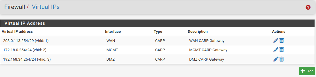
Carp List
To verify confiuguration, go to Status → CARP (failover) on both nodes.
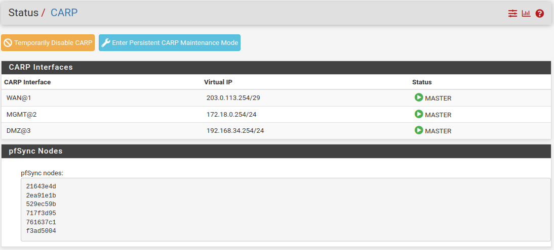
CARP Staus Primary Node
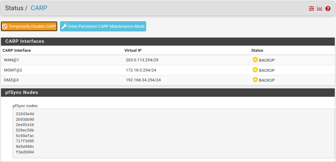
CARP Staus Secondary Node
There is two button:
and
The first one change the role from MASTER to BACKUP until the node was rebooted or when the new button is pressed.
The second one change the role from MASTER to BACKUP in a persitent mode, for return to MASTER role need to press the new button
Attention
When you use those buttons you must login to admin page not on CARP Interface but on the single node ip address, it is also a good practice to change the theme of the administration interface of the secondary nodes to understand on the fly where you are operating.
Configure Outbound NAT
When CARP is used it’s necessary to manual adjust Outbound NAT for use of CARP IPs insted of interface IPs.
Navigate to Firewall → NAT → Outbound.
- Mode:
Hybrid Outbound NAT rule generator.
This metod generate automatically NAT rule and it’s already possible to add/modify manual rules instead of automatic NAT rule generator.
Click
Now you must insert manual outbound NAT mappings, click  Add.
Add.
- Interface:
WAN
- Address Family:
IPv4
- Source:
MGMT subnet
172.18.0.0/24- Traslation->Address
WAN CARP Gateway
203.0.113.254- Description:
MGMT to WAN
Click
Now click Add.
- Interface:
WAN
- Address Family:
IPv4
- Source:
MGMT subnet
172.18.0.0/24- Destination:
- Type:
Any
- Port:
500
- Traslation:
- Address:
WAN CARP Gateway
203.0.113.254- Port or Range:
Check Static
- Description:
ISAKMP to WAN
Click
The first rule permit to translate MGMT IPs to CARP WAN Gateway instead of single interface IP. The second rule is for connection to external IPSEC VPN.
Continue by creating the two rules for the DMZ interface, taking care to modify the Source field with the network 192.168.34.0/24.
The Automatic Rules remain in configuration only for the network than not mapped in Mappings, this section overlaps the default rules.
When complete the result look like this:
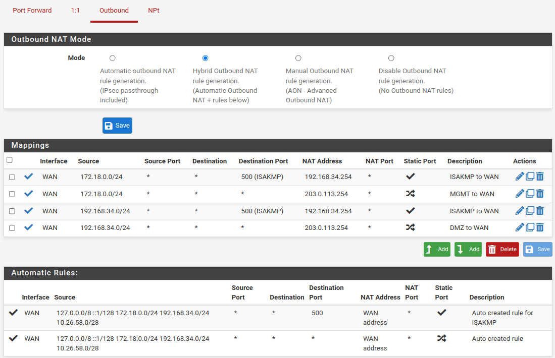
Outbound NAT Rules
Adjust DHCP Server
Modify DHCP configuration on Primary for make service in HA. This setup need to be make on all interfaces with DHCP activated.
Go to Services → DHCP Server → MGMT.
- DNS Server:
MGMT CARP Gateway,
172.18.0.254- Gateway:
MGMT CARP Gateway,
172.18.0.254- Failover Peer IP
MGMT Secondary interface ip,
172.16.0.252
Click
The Secondary will automatically adjust Failover Peer IP with correct value, 172.18.0.253
Warning
Those changes need to make on all interface that have DHCP Server activated and a CARP interface.
Testing HA
Login on Primary Node by node ip address and not by CARP Ip.
On another browser tab login on Backup Node by node ip address and not by CARP Ip.
Go to Primary Node tab.
It’s time to perform a test. Navigate to Status → CARP (failover).
There are two buttons; and , respectively;
CARP will be disable until reboot of the Node or when the new button is pressed.
CARP remain disabled until the button is pressed.
Tip
is necessary when perform a system upgrade of a node or when makes change on interfaces.
Test One
Make an infinite ping to google DNS 8.8.8.8 from management pc.
On Primary Node click on button , if all works as aspected, you don’t will lost any ping and the Status column will go in BACKUP.
On Secondary Node the Status column will go in MASTER.
If all works as aspected, you don’t will lost any ping.
Test Two
Make an infinite ping to google DNS 8.8.8.8 from management pc.
On Primary Node go to Diagnostics → Reboot. Select Normal Reboot and press Submit.
After reboot as finished the Primary Node will return as MASTER.
If all works as aspected, you don’t will lost any ping.
Test Three
Make an infinite ping to google DNS 8.8.8.8 from management pc.
Perform a hot shutdown of Primary Node by removing the power supply.
If all works as aspected, you will lost only one or two ping.
Tip
If all works as aspected you must perform a configuration backup of all nodes.